-
KEMAR >
-
-
-
-
-
-
-
R&D
-
PE
-
PL, QA and QC
-
-
-
-
Got a question?
If you have a question, feel free to contact us:
GRAS Sound & Vibration
Headquarter | gras@grasacoustics.com
UK | sales-uk@grasacoustics.com
USA | sales-usa@grasacoustics.com
China | cnsales@grasacoustics.com
South Korea | sales-kr@grasacoustics.com
India | sales-in@grasacoustics.com
GRAS worldwide

Engine Noise Testing
A lot of noise originates from the engine itself of course, the gear box, the belt drive system, pumps, cooling fans, but also other components like the A/C compressor and the power steering motors. These systems contribute to the vehicle acoustic comfort and some parts of the noise provides important feedback to the driver while other parts are just annoying.
The noise from the engine bay can also affect the external noise (the pass-by noise), which is regulated by law. Vehicle interior measurements form the basis for verifying the vehicle performance, and the measurement procedures are developed to provide analysis results that correlate with the subjective impressions.
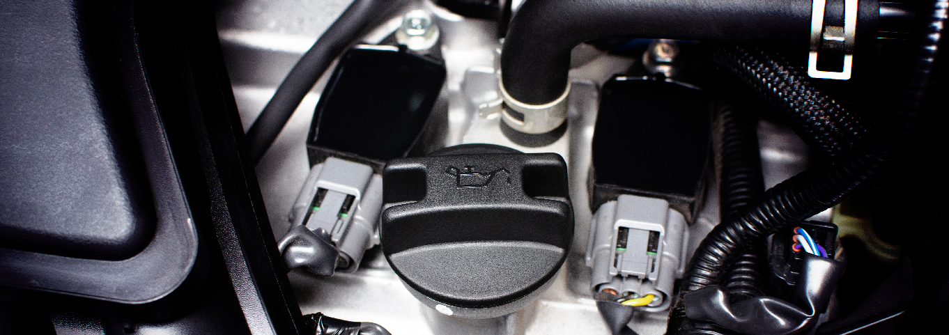
Measurements in the engine bay will provide detailed information about the noise to identify e.g. source location, source strength, frequency content, engine order content and time variation, and will explain the physical cause of the noise. This result will guide the engineers as to how to reduce unwanted noise.
Engine bay measurements in combination with interior or exterior measurements will provide information about the performance of acoustic packages and how well they work. These packages provide sound insulation or sound absorption.
The measurements will be done both on the OEMs development test vehicles and on the production follow-up vehicles as well as for benchmarking to make sure that the customer’s expectations for a new vehicle can be fulfilled.
Learn more about the challenges and how to select the right microphone
Resources
Selected products
-
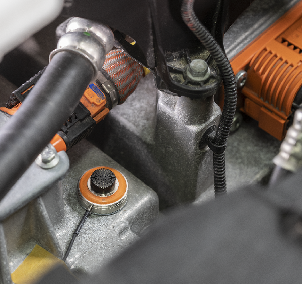
GRAS 147AX
A rugged surface microphone with an ingenious mounting system for repeatable cold and hot engine testing – also on the proving ground -
GRAS 146AE
The perfect choice for inside car testing -
GRAS 42AG
The ideal solution for calibration
Engine Noise Testing on Electric Vehicles
Since there is no low-frequency engine noise in EVs, many other noises are not masked. On the contrary, new high-frequency tonal noise from the electric motor and the inverter is very disturbing. Especially at high speeds, the motor will start howling, and although this is at low sound pressure levels, it can be quite annoying for the driver.
On electric vehicles, it is increasingly important to be able to perform good measurements at higher frequencies. In an environment with more high-frequency content, extra care has to be taken in order to measure and map the distribution of content reliably.
Thus, it is more important to identify the appropriate measuring positions and being able to repeat and reproduce the measurements over time.
There is no apparent need for a low-noise type microphone when measuring engine noise in the engine bay. We recommend GRAS 147AX CCP Rugged Pressure Microphone, which has a dynamic range well suited for that environment. GRAS 146AE ½” CCP Free-field Microphone Set can be used as a reference microphone.
See our complete application offering within electric vehicles here.

ACOUSTIC TEST TYPES WITHIN ENGINE NOISE TESTING
Measurements in the engine bay area include:
- Near-field measurements close to the different sources
- Far-field measurements for sound power estimations
- Sound intensity measurements
- Microphone arrays for sound source location
- Acoustic transfer function (ATF) measurements
Near-field measurements
The near-field measurements are best done at standardized positions distributed in the engine bay and close to where the noise sources are located. The measurement result can be used as a noise indicator and for comparison with other test vehicles. A single position selected from many microphone positions can be found to be a good indicator for the problematic noise during measurements at operating conditions. This result will then be used for verification of different engine calibrations for example.
Far-field measurements
Far-field measurements for sound power estimation are performed in a hemi-anechoic chamber equipped with a low-noise, vibration and harshness (NVH) chassis dynamometer. Engineering methods require few measurement microphones, three to four can be used, while precision methods require a minimum of 20 measurement microphones. The microphones are typically positioned in a hemisphere around the engine, and the sound power versus frequency is calculated.
Sound intensity measurements
Sound intensity measurements can be used for noise source location. This is mostly done in a NVH hemi-anechoic test chamber in combination with other NVH vehicle testing, but can be performed at other locations as well since the intensity technique is quite tolerant to the acoustic environment. This type of testing is mostly suitable for engine operating conditions at idle or at fixed engine rpm and gear in neutral. The result is a ranking of the different sources at different frequencies. Countermeasures with improved engine covers can easily be verified this way.
Microphone arrays for sound source location
Microphone arrays can also be used for noise source location in a hemi-anechoic chamber equipped with NVH chassis dynamometer. The array can be installed above the engine bay and allows for safe testing at driving conditions without any person outside the vehicle. Different techniques for analysis such as beamforming and acoustic holography are available and the result can be visualized in real-time.
Acoustic transfer function measurements
The ATF testing is used to capture an average insertion loss, and the result will be used for:
- Verification of vehicle requirements
- Comparison to benchmarks
- To estimate noise levels in the vehicle interior from the sound power of the source
- Computer-aided engineering (CAE) correlation
These measurements need careful instrumentation since the result is determined as an average of several paths. The sound source is moved between several locations and the response is also measured at several positions in the engine bay. It is common to have up to 12 source locations and 36 response positions, so the final number of measurements can be several hundreds. The number of responses to measure is chosen as needed depending on test time and accuracy.
Since more and more electric vehicles are being introduced, the possibility to perform good measurements at higher frequencies is increasingly important. Electric motors with control system and gearboxes will produce tones at higher frequencies compared to the internal combustion engine. Read about electric applications here.


