Frequently Asked Questions
Mouth Simulators
Can I mount 44AA or 44AB mouth simulators inside the KEMAR head?
No, 44AA and 44AB mouth simulators won’t fit inside a KEMAR Head. The KEMAR´s mouth simulator has a smaller housing, custom made to fit the small cavity inside the KEMAR head. It also requires custom fitting to ensure proper sealing between the mouth simulator and the KEMAR lips.
A 45BC KEMAR has an audio amplifier for the mouth simulator, located inside the torso. Therefore, if a KEMAR with mouth simulator is used without its torso, an external audio amplifier will be needed.
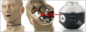
Figure 1. 44AA/AB mouth simulator CAN´T fit inside a GRAS 45BC KEMAR´s head.
Can_I_mount_44AA_or_44AB_mouth_simulators_inside_the_KEMAR_head.pdf
Calibration
What is the difference between a pistonphone and a sound calibrator?
Pistonphones and sound calibrators are instruments designed for sensitivity checking and calibration of measurement microphones. In order to do that, these instruments can produce a reference signal at a specific level and frequency. Even though both instruments share the same goal, there are some key differences in the use, working principles and applications, that need to be considered.
A Pistonphones is a precision sound source for accurate and reliable calibration of measurement
microphones. It produces a reference signal using the mechanical movement of two reciprocated pistons actuated by a precision-machined cam disc with a sinusoidal profile (Figure 39).
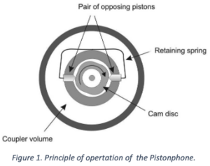
Figure 1. Principle of opertation of the Pistonphone.
Pistonphones have calibration couplers (Figure 40) with a very well defined volume. The
pistonphone is calibrated so it produces a certain reference signal (i.e. 114dB @ 250 Hz) with a
specific type of measurement microphone at specific environmental conditions (temperature, static pressure and humidity). At these reference conditions, the pistonphone can have a calibration accuracy of +/- 0.09 dB.
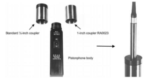
Figure 2. Left: Pistonphone with 1” and ½” calibration couplers. Right: ½” microphone set inserted in pistonphone´s calibration coupler.
When a microphone with different dimensions is inserted in the calibration coupler, the volume of
the coupler will change compared to the original reference volume. When this happens, the sound pressure level inside the calibration coupler will change due to the air volume modification. Therefore, it will be necessary to apply corrections to the measured results to compensate for the internal volume change and being able to perform an accurate calibration.
The same happens when the environmental conditions differ from the refence conditions. The
measured results can be corrected for the deviations in static pressure, temperature and humidity from the reference conditions.
The pistonphone is an expensive and extremely accurate piece of equipment usually reserved for laboratory use. The pistonphone has to be operated by an expert who knows how to apply the volume and environmental corrections in order to take advantage of its calibration accuracy.
Sound calibrators, on the other hand, are less expensive and less accurate, but easier to operate
compared to pistonphones. The principle of operation is also completely different, reliying on the
use of an internal sinus generator circuit, amplifier and loudspeaker.
This simple design allows this instrument to be able to produce 1 or more different tones at different levels, so the calibration can be performed with different calibration signals. As an example, GRAS 42AG has two calibration frequencies (250 Hz and 1000 Hz) and two levels (94 dB and 114 dB).

Figure 3. GRAS 42AG Sound Calibrator.
Another great advantage of the sound calibrator is that it uses an internal microphone that
measures the sound pressure level in the calibration chamber. This data is used by a feed-back and control circuit to correct for any deviations from the stablished sound pressure level due to changes in the internal volume, static pressure, temperature or humidity. This means that the operator won´t need to apply any manual compensations after calibration to get an accurate result, making sound calibrators very easy to use.
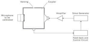
Figure 4. Simplified block diagram illustrating typical sound calibrator´s principles of operation
Sound calibrators are less accurate than pistonphones. A typical calibration accuracy for a sound calibrator is +/- 0.2 dB. They are also less expensive and ligther in weight compared to a
pistonphone, which makes them the ideal field sensitivity calibration instrument.
What_is_the_difference_between_a_pistonphone_and_a_sound_calibrator_.pdf
My microphone has been calibrated some years ago. Can I still trust the calibration or should it be re-calibrated?
A measurement microphone that is stored in a controlled laboratory environment that was never
exposed to challenging environments, shocks, drops or vibrations, can keep its sensitivity and
frequency response stable for many years. However, calibration at regular intervals is a way to
safeguard the quality of your measurements and to eliminate the costs caused by unreliable
equipment. Also, it is a way to ensure that historical measurement data is valid and comparable.
Depending on the use, measurement environment, and internal quality control programs, we
recommend that microphones are calibrated at a dedicated calibration laboratory at least once a
year.
We endorse our ISO/IEC 17025 Accredited Calibration Laboratory in Denmark and the GRAS
Microphone Calibration Centers located in Asia, Europe and North America.
How can I get the calibration data from the TEDS chip? Is it possible to freely read and write the TEDS chip data?
TEDS (Transducer Electronic Data Sheet) is a set of electronic data in a standardized format defined within the IEEE 1451.4 standard. This data specifies what type of sensor is present, describes its interface, and gives technical information such as manufacturer, type number, serial number, sensitivity, calibration date, reference condition, etc. A TEDS sensor is the same as a "plug-and-play sensor”. Via its internal memory, it can identify and describe itself to the data acquisition system and perform automatic system configuration.
Most GRAS sensors are equipped with a TEDS chip inside the preamplifier (both in Traditional and CCP types). This chip can be a Dallas DS2430 (already discontinued) or the newest Dallas DS2431. You can double-check if your GRAS sensor has a TEDS chip inside by looking at the specification of the product in our website. When a GRAS sensor is sold as a set (for example: microphone + preamplifier), the TEDS chip inside the preamplifier will contain all the important information from the sensor, including the calibration data.
Preamplifiers sold separately can also have a TEDS chip inside. You can check the preamplifier´s
specifications in our website to check if it has a TEDS chip. In preamplifiers sold this way, the TEDS chip is going to be blank and ready for writing data.
In order to read and write a TEDS chip it is necessary to have software and hardware compatible
with the technology. Most of the Data Acquisition Systems (DAQs) and software related to sound
and vibration measurements available nowadays are already compatible with TEDS.
If you have problems reading a TEDS chip with equipment that claims to be TEDS compatible, ask the manufacturer about the compatibility with the newest Dallas DS2431 chip. In some cases, a simple software update might solve the issue.
All equipment TEDS compatible can read the information written in the chip, but not all hardware
and software has the capability of writing data. You should ask the equipment manufacturer about these capabilities.
Every GRAS microphone sold as a set (microphone + preamplifier) will have data written in the TEDS chip. This is the typical data stored and structure used in TEDS-compatible GRAS sensors:
| Basic TEDS | Manufacturer ID | |
| Model Number | ||
| Version Letter | ||
| Version Number | ||
| Serial Number | ||
| Standard TEDS | Calibration Date | |
| Sensitivity @ 250 Hz | ||
| Prepolarized 0/1 | ||
| Microphone Type | ||
| Polarization Voltage | ||
| Microphone Size | ||
| User TEDS | i.e. Measurement Position | |
The basic TEDS data is stored in a programmable read-only memory (PROM). That means that once the data is written, it cannot be changed or erased. The rest of the data is written in an electronically erasable programmable read-only memory (EEPROM), that can be programmed by the manufacturer or any user that has TEDS-compatible equipment with writing capabilities.
There are other types of TEDS chips available that have the capability to store more data but are still not common in the market, still not supported by most DAQ manufacturers and therefore not
covered here.
Should I use a correction factor with my pistonphone or calibrator when calibrating my ear simulator?
Every ear simulator/coupler has a different design and calibration method. There are some ear
simulators that can even be calibrated in different ways, by adding calibration adapters between the calibrator and the device. Therefore, it is of paramount importance to first read the calibration section of the product´s manual to check for the calibration procedure and calibration correction factors, if any. For example, in couplers like the 2cc (GRAS RA0038, RA0113 and 43AB) the calibration with pistonphone or sound calibrator is performed on the microphone itself, WITHOUT the coupler. In this case, the calibration is performed like a standard microphone set calibration. The same happens for IEC 60318-1 coupler (GRAS RA0039 and 43AA):

Figure 1. 2cc and IEC60318-1 test fixtures are calibrated without the ear simulator/coupler, but performing a direct microphone calibration. In this particular case, the GRAS 42AA/AP pistonphone has to be set up without its retention collar (See manual).
On the other, in a 711 style ear simulator (like GRAS RA0045, RA0401/2 and RA0403/4), the
microphone is built into the device and can´t be removed for calibration with pistonphone or sound calibrator. Under this circumstances we will be forced to perform the calibration with the coupler. When using a pistonphone, this will mean that an extra air volume will be added to the one on the calibration coupler and we will need to correct for it. On a sound calibrator, it will mean that the microphone capsule inside the 711 style ear simulator will be outside the calibration cavity where the feed-back and control circuit is controlling the calibration sound level. The microphone inside the ear simulator is also separated from the calibrator by a cylinder, where standing waves can affect the calibration when using reference frequencies of 1000 Hz or higher. A 711 syle ear simulator doesn’t have a flat frequency response at these frequencies either. This means that depending on the calibration device used and reference frequencies, we will need to apply calibration correction factors due to all the reasons mentioned above.

Figure 2. 711 style ear simulators (like the one include in GRAS 43AC) have a buil-in non-removable microphone that has to be calibrated together with the coupler which will create the need of using correction factors when calibrating with a pistonphone or sound calibrator.
GRAS KEMAR head and torso simulator has many configurations where 711 style ear simulators are used. On the table below it is possible to see that, depending on the calibration setup and frequency used, we will have to use different correction factors for the calibration:

Figure 3. Correction factors for KEMAR with 711 syle ear simulators (RA0045 and RA040X series). The values change depending on the calibration device (42AA/AP pistonphone or 42AG sound calibrator), the reference frequency (250 or 1000Hz) and the way of mounting the ear simulator to the calibration device (with/without adapters)
Acoustical Test Fixtures
Can I configure KEMAR for measurements of active-noise-cancellation (ANC) and Bluetooth headphones/headsets electrical circuit hiss noise?
Yes, it is possible. Active Noise Cancellation and Bluetooth headphones/headsets tend to have a “hiss” noise in quiet surroundings. This “hiss” can be detected via subjective testing, but when it comes to objective measurements, this phenomenon cannot be measured with traditional ear simulators, like the 60318-4 Ear Simulator (aka 711 coupler) or standard measurement microphones. This is because standard ear simulators and microphones have a noise floor around 20 dBA, which is usually higher than the hiss noise produced by the ANC or bluethooth circuitry. This is why, even though the human ear can hear this noise, regular measurement microphones and ear simulators can`t measure the signals.
GRAS offers a special type of 711 style ear simulator with Low-noise specifications, the GRAS 43BB-1 Low-noise ear simulator. This ear simulator can be mounted on a KEMAR head and torso simulator (HATS) to perform measurments down to 10.5 dBA.
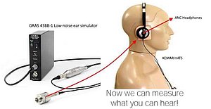
Figure 1. GRAS 43BB-1 Low-noise ear simulator can be mounted inside a KEMAR HATS for low-noise measurements down to 10.5 dBA.
Below there is a chart showing an ANC test performed with ANC Headphones using a GRAS KEMAR head and torso simulator (HATS):
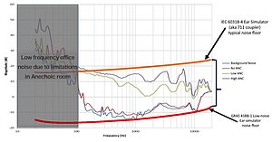
Figure 2. ANC Test performed with ANC supra-aural headphones on KEMAR HATS with low-noise ear simulators.
The orange curve on the top shows the typical noise floor curve of a IEC 60318-4 ear simulator (aka 711 coupler). Dark red and blue curves show the background noise measured inside the anechoic chamber using the KEMAR HATS with and withouth the headphones, respectively. When the ANC headphones are turned on, the hiss noise can be heard. This noise is noise generated by the internal circuitry itself when the ANC is turned on (no reference signals or music is being played through the headphones). The violet and green curves show the hiss noise profiles when using the Low and High ANC circuits available in these headphones.
All the measured curves in the chart above, are below the noise floor of a typical IEC 60318-4 ear simulator. This means that a standard ear simulator with regular measurement microphones will not be sufficient to measure any of the signals measured above. On the other hand, the bright red curve is showing the noise floor of a 43BB-1 low-noise ear simulator. With a system like this mounted in a KEMAR HATS, it is possible to measure ANC and Bluetooth circuits hiss noise.
43BB-1 Low-noise ear simulator can be used mounted in a KEMAR, but also inside a GRAS 45CA Test Fixture (ask Global Support for more information about this option) or standalone.
Can_I_configure_KEMAR_for_measurements_of_active-noise-cancellation__ANC__and.pdf
I have problems fitting in-ear headphones in the standardized pinna. How does it affect the accuracy of my measurements?
Standard/classic rubber pinnae (like GRAS KB0060/1 and KB0065/6) were originally designed for testing hearing aids or in-ear phones from communication devices with conical or cilindrical fittings:
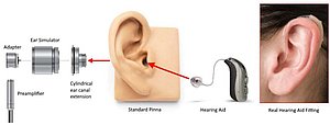
Figure 1. Standard pianne were designed to test hearing aids or in-ear communication devices with conical or cylindrical fittings.
Under the mentioned conditions, having an extremely realistic model of the ear pinna wasn´t a main goal, as the testing wouldn´t really benefit from it.
The ear canal extension connecting the pinna to the ear simulator, as shown in the figure above, is either cylindrical or conically shaped and thus far from the complexity of a human ear canal. While the cylindrical ear canal is relevant for testing hearing aids (often paired with a standardized ear mold), it can be difficult to obtain reliable, repeatable measurements with anthropometrically shapped in-ear and ear-bud headphones and in-ear hearing protectors. Furthermore, the compliance and pliability of the standardized pinna may be accurate in one dimension, but definitely not when it comes to collapsing towards the head. This presents an added obstacle when measuring devices intended to go on or over the ear. This is because the pinna protrusion and stiffness can prevent a good seal and therefore an accurate measure of low frequency performance – both in terms of audio reproduction and ambient noise reduction.
To overcome the above mentioned limitations, GRAS has developed a family of anthropometric pinnae (KB5000/1/2 and KB5010/1). These pinnae were modeled from 3D scans of around 300 real human ear canals. The result is a pinna with a more realistic oval ear entrance point that includes the 1st bend and all the way to the 2nd bend of the human ear canal. In addition to the anatomically correct ear canal, the anthropometric pinna has been made with softer materials to provide better and more realistic flexibility of the outer ear.
All these characteristics will provide more realistic fit for anthropometric shaped in-ear headphones, hearing aids, hearing protectors but also supra aural headphones (due to the more realistic collapsibility of the pinna):
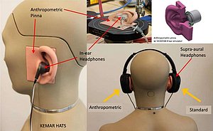
Figure 2. GRAS anthropometric pinna vs standard pinna for headphone testing.
In reality, the use of anthropometric pinna will provide a better fit and sealing that will contribute to the repeatability and overall quality of the test results. The example below shows the results for a frequency response test of anthropometrically shaped in-ear headphones (Figure 36 Left) with standard vs anhropometric pinna mounted on a KEMAR HATS. The in-ear headphones were mounted and dismounted 11 times for each pinna type:
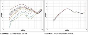
Figure 3. Frequency response test results spread comparison between standard pinna (left) vs anthropometric pinna (right).
The improved fitting and sealing obtained with the anthropometric pinna results in a clear improvement of the measurements repeatability in the entire frequency range of the test.
I_have_problems_fitting_in-ear_headphones_in_the_standardized_pinna._How_does_it.pdf
Preamplifiers
Why do I need a preamplifier?
The output from a condenser microphone is a very high-impedance signal and is therefore very sensitive to the capacitive loads of cables. This makes it necessary to introduce a driver with high input impedance and low output impedance. Such a driver is called a preamplifier and it actually prepares the output signal of the microphone to be able to be fed into a cable and travel with minor or no losses at all for many meters up to the data aquisition system.
Even tough it is called preamplifier, not only it doesn’t amplify the signal coming from the microphone, but it usually reduces its gain. Typically, most preamplifiers have a gain of around -0.3 dB.
What is the difference between Traditional (LEMO) and CCP preamplifiers?
Just like with microphone capsules, there are also two main types of preamplifiers that are used together with measurement microphones. The difference between these two types lie in the type of power supply needed to drive the internal circuitry of the preamplifier. Unlike microphone capsules, where Prepolarized capsules don’t need an external supply to work, preamplifiers will always require an external supply to work. It is possible to classify preamplifiers into two main types:
- Traditional: They are referred as Traditional preamplifiers since it was the first technology used for measurement microphones. They are voltage driven, using both single sided and dual sided power supplies (some preamplifiers will support both types of supplies like +/-15V, +/-60V, +28V and +120V). They are also referred as “LEMO” type, given the fact that they are typically equipped with multi-pin LEMO style connectors for multi-wire cables. This multi-pin connector will carry the signal out of the microphone, carry the preamplifier supply, microphone capsule polarization voltage, etc. in different wires separately (see Figure 11).
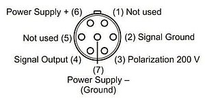
Figure 1. 7-pin LEMO style connector layout for Traditional type preamplifier.
Figure 2. Left: ½” Traditional preamp with 7-pin LEMO style connector. Middle: ¼” Traditional preamp with 5-pin LEMO style connector. Right: ¼” Traditional preamp with 4-pin LEMO style connector.
Traditional preamplifiers are typically using variations of multi-pin LEMO style connectors like 4, 5 and 7-pin and multi-wire cables (Figure 12).
It is important to note that Traditional Preamplifiers can be used with both externally polarized and Prepolarized microphone capsules.
GRAS examples: 26AA, 26AB, 26AC-1, 26AK and 26AS.
- Constant Current Powered (CCP): Also known as IEPE (Integrated Electronic Piezo-Electric), ICP (Integrated Circuit PiezoElectric) and CCLD (Constant Current Line Drive). It is compatible with many other constant current driven products such as Deltatron®, Isotron, etc. The CCP principle is a two-wire system using one wire for both the constant current supply for the preamplifier and the signal output. The signal is superimposed on the wire through which the current is kept constant. The other wire is used for ground connection. A CCP preamplifier uses a Constant Current Power supply, which must be between 2 mA and 20 mA (nominally 4 mA), to produce a constant nominal voltage level of 12 Volt DC (referred to as the bias voltage) to drive the preamplifier. The output signal from the microphone superimposes fluctuations around the DC level.
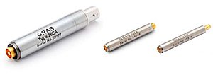
Figure 3. Left: ½” CCP preamp with BNC connector. Middle: ¼” CCP preamp with Microdot 10/32 connector. Right: ¼” CCP preamp with SMB connector.
CCP preamplifiers are typically using BNC, Microdot 10/32 and SMB connectors with coaxial cables (Figure 13).
CCP preamplifiers can ONLY be used with Prepolarized microphone capsules.
GRAS examples: 26CA, 26CB, 26CC, 26CF and 26CK.
What_is_the_difference_between_Traditional__LEMO__and_CCP_preamplifiers.pdf
Ear Simulators
Are the RA0401 and RA0402 High Frequency Ear Simulators fulfilling the IEC 60318-4 standard?
Yes, both RA0401 and RA0402 711 style ear simulators from GRAS are an improved version of the classic RA0045 and RA0045-S1 ear simulators. They fullfil all the specifications from a classic “711” ear simulator mentioned in the IEC 60318-4 standard, like same physical dimensions, the use of a ½” pressure microphone and frequency response tolerances.
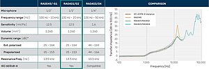
Figure 1. Comparison between the classic RA0045 ear simulator against RA0401/2 and RA0403/4 new family of ear simulators.
The RA0401/2 ear simulators are even keeping the same 13.5 kHz resonance caused by the main air volume in the coupler. A great advantage of the RA0401/2 is that they are adding damping system that attenuates the half-wave resonance at 13.5 kHz. Thanks to this, it is possible to extend the upper frequency range limit from 10 kHz up to 20 kHz. We also added frequency response tolerances from 10 kHz up to 20 kHz, that were inexistent before. IEC 60318-4 provides tolerances from 100 Hz and up to only 10 kHz, which means that there can be huge differences in frequency response from coupler to coupler when measuring above 10 kHz. This will no longer be a problem with RA0401/2 ear simulators.
To sum up, RA0401/2 High Frequency ear simulators use the same ½” microphone as the original version and fully complies with the standard. This is why we recommend it as the first choice when you are looking for a “standard” 60318-4 ear simulator - but without its shortcomings at high frequencies. We think of it as “the new normal”
Are_the_RA0401_and_RA0402_High_Frequency_Ear_Simulators_fulfilling_the_IEC_60318-4.pdf
Are the new RA0403 and RA0404 Hi-Res ear simulators better than the RA0401 and RA0402 High-Frequency ear simulators?
RA0403 and RA0404 Hi-Res ear simulators are not neccesarily better or worse than RA0401 and RA0402 High Frequency ear simulators. Using RA0403 and RA0404 ear simulators can have some advantages but also disadvantages depending on the application:

Figure 1. Comparison between RA0401/2 High Frequency ear simulators VS RA0403/4 Hi-Res ear simulators. Green indicates an advantage against the other ear simulator, while red indicates disadvantage.
RA0403/4 Hi-Res ear simulators has a damping system that attenuates the length-related resonances above 10 kHz. The use of a ¼” microphone also extends the useful frequency range to 50 kHz and beyond. The 60318-4 standard calls for a ½” microphone and this is the only reason why the Hi-Res Ear Simulator is not standard-compliant, but ”only” standard-compatible, as it fully complies with the standard in all other respects.
The use of a less sensitive ¼” microphone capsule allows the RA0403/4 to be used to measure up to higher sound pressure levels compared to RA0401/2. The lighter diaphragm from the ¼” microphone will also allow us to use the Hi-Res simulator to test up to higher frequencies. The disadvantage is that, due to its reduced sensitivity, a ¼” microphone will have a higher noise floor compared to a ½” capsule.
In summary, RA0403/4 is ideal for reliable testing above 10/20 kHz and up to 50 kHz (ideal for HiRes certification). Testing under high sound pressure level conditions up to 166/169 dB is also a plus, but at the expense of increasing the noise floor to 44 dBA.
Are_the_new_RA0403_and_RA0404_Hi-Res_ear_simulators_better_than_the_RA0401_and.pdf
Microphones
I have an application where I only have space for the microphone capsule. Can I connect my microphone (capsule) directly to my DAQ?
Connecting a microphone without a preamplifier is NOT the best idea. The Output of the microphone capsule is extremely high, 20GΩ or higher, while a standard DAQ typically has an input impedance of 100 kΩ– 1MΩ
For 100 kΩ = 1/200000
For 1 MΩ = 1/20000
With a sound pressure level of 94 dB, the output of a standard ½” microphone capsule is 50 mV. If a pre-polarized capsule is mounted directly to the DAQ, the DAQ will see a signal level of:
With DAQ 100 kΩ: 250 nV
With DAQ 1 MΩ: 2.5 µV
The level is very small, and therefore also very sensitive for EMC, as you have no protection of the microphone output. So, to conclude: Connecting a microphone capsule directly to a DAQ will not work.
What is the maximum recommended length for a microphone cable before it affects the signal (CCP or traditional-powered)?
A cable behaves like a capacitor. Its capacitance can be calculated with the formula
CCable=C per meter × Length of Cable in meter
As the impedance of a capacitor is frequency-dependent, the cable load will be higher at high frequencies. The longer the cable is, the higher the capacitance will be, meaning that the cable load will start having influence at lower frequencies. Therefore, the lower the upper frequency range will be, as shown on the figure below.
The influence is also dependent on the SPL Level measured. Relatively low SPL levels give a relatively lower output voltage of the microphone and therefore a lower current is necessary, while a high SPL value gives a high voltage and a much higher current is necessary. The maximum SPL level that can be measured can be computed with the following formula:
Using longer cables will therefore be more critical if the preamplifier current consumption is higher. To give an idea of the typical supply current values, a traditional LEMO Power Module for a measurement microphone is normally able to deliver 5 – 7 mA and a CCP Power Module can deliver typically 4 mA. The preamplifier current consumption is usually around 1-2 mA, meaning that the user will have 2-3 mA to drive the cable.
To sum up, the maximum recommended length for a microphone cable before it affects the signal will depend on the maximum frequency and sound pressure level you are expected to measure. Having long cables will restrict the upper dynamic range as well as the upper frequency limit, so the cable’s length choice will depend on these parameters.
It’s always a good thing to remember that when the distance between the microphone and the DAQ is very long, it is preferred to keep the distance between the microphone set and the power module as low as possible and have longer cables between the power module and the DAQ.
I dropped my microphone on the floor. How does it affect the sensitivity and frequency response?
Even though GRAS microphones are tested for Vibration and Mechanical Impulsive Stress tests during our HALT (Highly Accelerated Lifetime Test) procedure, every time a microphone set is dropped on the floor, there is the possibility of damage.
Depending on the violence of the impact, the damage can go from only aesthetic to complete failure. Impacts on the microphone capsule can destroy the microphone´s diaphragm or cause change in sensitivity. Therefore, it is nececesary to visualy inspect the capsule after a drop and look for holes in the diaphragm (after carefully removing the protection grid). If no holes are found in the diaphragm, we can perform a sensitivity test with a sound calibrator or pistonphone. The measured sensitivity has to be compared with the previous calibration or the data in the calibration chart to check for abnormal changes.
A sensitivity change due to microphone drop doesn’t necessarily mean that the microphone is not usable any longer, as it can be permanent but also stable over time.
If after the fall, there is no electrical output from the microphone set, there can be damage in the preamplifier’s internal circuitry.
Whatever the case, if there are signs of damage or sensitivity change, it is advised to ship the unit back to our workshop, so our experts can check the extent of the damage.
I_dropped_my_microphone_on_the_floor._How_does_it_affect_the_sensitivity_and_fequency_response.pdf
What are the different types of microphones available depending on the type of soundfield?
Choosing the right measurement microphone is essential for obtaining useful measurement data. The different types of microphones are designed for different types of sound fields. Understanding the differences between the microphones can help the user to select the right microphone and avoid possible measurement errors.
Typically, the sound field is complex and therefore it is important to understand the relationship between the microphone and the acoustic surroundings. A sound field with many reflections and standing waves can be a challenge. Whether it is free-field, diffuse-field or something in between, a reasonable choice of the measurement microphone makes post-processing and analysis of the data much easier.
Determining what type of sound field is present is also important for choosing the right microphone for the measurement and getting reliable results. The three different ideal sound fields are described as follows:
A. Pressure field
A pressure field is defined as the sound field on a surface or a small closed chamber, where the phase and magnitude are the same throughout. This could be the inside of a wind tunnel, small cavities, boundary layers or acoustic couplers.
B. Free field
A free field is defined as a sound field without any objects that can introduce reflections. So the only sound arriving to a microphone/listener in this sound field is the direct sound without the influence of any reflections. Assuming a single monopole sound source, the sound field can be approximated to simple plane waves radiated in a well-defined direction. A loudspeaker in an anechoic chamber can be considered a free-field situation in a limited frequency range determined by the size of the chamber.
C. Diffuse field
A diffuse field, or random incidence field, has sound arriving with equal probability and level from all directions. It can be a room with many objects causing reflections in many directions (see standard IEC 61183 Random Incidence and diffuse field calibration of sound level meters). In practice, reverberant chambers for acoustic testing try to replicate a diffuse field within a limited frequency range.
Given the 3 above mentioned sound fields, it is possible to define 3 main different types of measurement microphones available in the market:

Figure 1. Left: Pressure microphone mounted in an enclosure with an angle of zero degree relative to source. Middle: Free-field microphone in an angle of zero deg relative to source. Right: Random incidence microphone with illustration of sound coming from all directions
A. Pressure microphones
A pressure microphone is designed to measure the actual sound pressure on the surface of the diaphragm of the microphone. This means that if the microphone is somehow disturbing the sound field and causing a diffraction effect, the microphone will measure that and the measurement results will be affected. Therefore, pressure microphones are typically mounted on a boundary (e.g. a wall) or as a part of a closed volume as an ear simulator. Thus, it measures the sound pressure on the boundary itself (Figure 1 Left).
B. Free-field microphones
As explained before, placing an object in a sound field will cause some local disturbance to the sound field. The free-field microphone (Figure 1 Middle) is designed in such a way that it corrects for its presence in the sound field and measures the sound pressure as if the microphone was not present.
Free-field microphones are designed to measure the sound pressure as it was before the microphone was introduced to the sound field, therefore compensating for its disturbances caused to the sound field. Ideally, the presence of the microphone should not affect the measurement. The free-field microphone is designed so that the sensitivity of the microphone decreases with the same amount as the acoustical pressure increases in front of the diaphragm (due to the diffraction effect). This is obtained by increasing the internal acoustical damping in the microphone cartridge. The result is an output from the microphone, which is proportional to the sound pressure, as it existed before the microphone was introduced into the sound field. In other words, if we know exactly how the microphone is disturbing the sound field, then we can design a microphone with a frequency response that compensates for the disturbance it is creating. Blue curve in Figure 2 shows the typical pressure build up that occurs when pointing a pressure microphone directly to a sound source (due to diffraction effects). The black curve shows the pressure response of a free-field microphone. The pressure response of the free-field microphone is dampened in order to compensate for the pressure build-up at high frequencies. Therefore, if we use a free-field microphone in a free-field (e.g. anechoic chamber) and point the microphone directly to the sound source (0-degree incidence), the microphone will now have a flat frequency response (red curve).
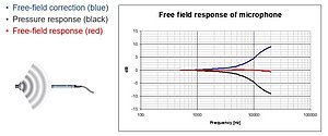
Figure 2. Typical pressure response, free-field correction and final free-field response of a ½” free-field measurement microphone.
It is very important to point out that this compensation will only work in a free-field environment at 0-degree incidence from a sound source.
Free-field microphones have been stablished as the standard microphone for acoustic measurements in many applications, even when we are not working in an ideal free-field situation.
C. Random-incidence microphones (also known as diffuse-field microphones)
In a random incidence sound field, where the sound comes from all directions with equal level, a random-incidence microphone should be used. This can be in a reverberation chamber or spaces with many reflecting surfaces (see Figure 1 Right).
What_are_the_different_types_of_microphones_available_depending_on_the_type_of_soundfield.pdf
What are the free-field and random incidence corrections? How should I use them?
Free-field and Random incidence (also known as diffuse-field) corrections are available for most GRAS measurement microphones. These values are showing how a specific microphone disturbs the sound field due to the diffraction effect.
Free-field and Random incidence corrections for most GRAS microphones can be found here in our website.
In order to obtain the free-field corrections of a microphone, the microphone under test is placed in a free-field environment and exposed to a well-known reference signal (like a logarithmic sine sweep). The microphone is first pointed at 0-degree incidence from a reference sound source with well-known frequency response. The frequency range for the test will depend on the frequency range of the microphone and its size. For example, a GRAS 46BE ¼” free-field microphone set has a frequency range from 4 Hz to 80 kHz, but will cause a sound pressure increase (due to diffraction effect) of less than 0.09 dB below 2kHz and no disturbance at all below 500 Hz. Once the results for 0-degree incidence are obtained, the microphone or sound source can be rotated to obtain results for different angles. As in reality there is no sound source that has a complete flat frequency response, we will need to compensate for the uneven response. We are interested in measuring the disturbances in the field caused by the microphone only and not the frequency response of our sound source. In order to differentiate which deviations are caused by the influence of the microphone in the sound field and which are caused by the bumpy response of our sound source, we will have to repeat the same measurement procedure we just did, but with a smaller microphone. A smaller microphone will move the diffraction effect to higher frequencies and therefore will allow us to precisely assess the frequency response of the sound source so we can compensate for its unevenness.
The procedure described above can be replicated in a diffuse-field environment (like a reverberant chamber) to obtain the random incidence corrections of a measurement microphone.
The free-field and random incidence corrections are typically used for two specific purposes:
1) Due to its convenience and ease of implementation, the electrostatic actuator method is one of the most common methods used to obtain the pressure frequency response of a measurement microphone. When calibrating a free-field or random incidence microphone, the pressure frequency response will be measured first and then its free-field/diffuse-field response will be calculated by adding the free-field/random-incidence corrections to the pressure response (See Figures 1, 2 and 3):
Calculated Free-field response = Measured Pressure response + Free-Field correction
Calculated Random incidence response = Measured Pressure response + Random incidence correction
Example:
Let´s say I´m calibrating a GRAS 40AE ½” free-field microphone capsule and I measure a pressure response -0.40 dB @ 2 kHz (referred to 250Hz). If the free-field correction @ 2 kHz and 0-degree incidence for that microphone is 0.46 dB, then I can calculate the free-field response as follows: Calculated Free-Field response (@2kHz, 0-deg) = -0,40 dB + 0.46 dB = 0.06 dB (referred to 250 Hz).
Then the corrected response in the entire frequency range can also be calculated.
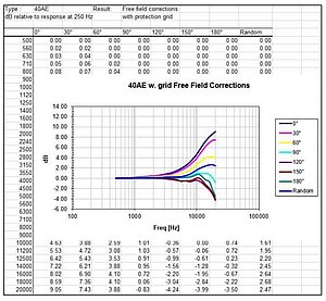
Figure 1. Typical Free-field corrections chart for a GRAS measurement microphone at different angles of incidence. Random incidence correction is also shown.
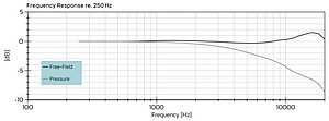
Figure 2. Measured pressure response and calculated free-field response of a free-field measurement microphone.
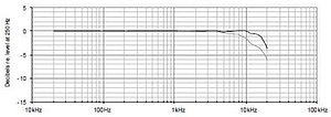
Figure 3. Typical frequency response of a random incidence microphone. Upper curve shows calculated response in a diffuse sound field (random incidence), lower curve shows measured pressure response.
2) When a pressure microphone is used in a free-field/diffuse-field environment, the diffraction effect will cause a pressure build up that will be measured by the microphone. If we have freefield/random- incidence corrections for that pressure microphone, then it will be possible to process the measured data to get rid of the pressured build up caused by the diffraction effect. This way, the postprocessed data will be the same as if the measurement was made with a free-field/randomincidence microphone:
Corrected response = Measured data with pressure microphone in a free-field environment – Freefield corrections
Corrected response = Measured data with pressure microphone in a diffuse-field environment - Random incidence corrections
Example:
I´m using a GRAS 46A0 ½” pressure microphone set in a free-field environment pointing at 60- degree incidence from my sound source. I´m measuring 75 dB @ 10 kHz. Free-field corrections from 46AO provided by GRAS shows that @ 10 kHz and 60-degree incidence the correction is 2.09 dB.
Then I can calculate the corrected response as follows: Corrected response (@ 10 kHz, 60- degree incidence) = 75 dB – 2.09 dB = 72.91 dB.
Then the corrected response in the entire frequency range can also be calculated.
What_are_the_free-field_and_random_incidence_corrections.pdf
How is the length of a cable affecting my measurement?
The preamplifier is a device that takes the high impedance signal coming from the microphone capsules and converts it to a low impedance signal that can be feed into long cables. So it is basically an impedance converter. But this doesn´t mean that I can use a 1 Km cable without expecting any signal loss. The cable can be seen as a low-pass filter that will change depending on the cable length. Other things that can influence the response of this low-pass filter are cable capacitance per meter and current available to drive the cable (coming from the preamplifier power supply). Below, it is possible to see different sets of curves for different cable capacitances:
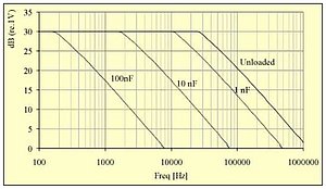
Figure 1. Cable influence in uppend dynamic range limit and high frequency range limit of a microphone.
The higher the capacitance, the lower the cut-off frequency for the low-pass filter. Higher capacitances can be associated with longer cables or different cable constructions. Typical microphone cables have a capacitance of around 100 pF/m.
The 0dB in the chart above represents 120dB (re. 1V) for a 50 mV/Pa sensitivity microphone capsule. Therefore we can say that the longer the cables used, the lower the upper dynamic range limit and high frequency range limit.
So, according to the chart, a 50mV/Pa with a cable load of 100nF will be able to measure up to approx. 137 dB @1000 Hz, but will be limited to approx. 129 dB @ 3000 Hz.
The signals travelling through the cables can also be affected by electromagnetic interference, noise due to grounding issues, etc. But that is another discussion.
Contact Global Support if you need help to calculate the influence of your cables.
What are the benefits and limitation of using Prepolarized microphones with CCP preamps vs. Externally polarized microphones with Traditional preamps?
We will explore the benefits and limitations of the CCP preamplifier and Prepolarized microphone technologies so it is possible to make a comparison with the performance of Traditional preamplifiers and Externally Polarized microphone capsules.
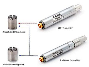
Figure 1. Possible connections between CCP/Traditional Preamplifiers and Externally polarized/Prepolarized microphone capsules.
Figure 14 shows the connection possibilities between Prepolarized and Externally polarized microphone capsules with CCP and Traditional preamplifiers. A traditional preamplifier can be used with both Prepolarized and externally polarized microphones. When a traditional preamplifier is used in combination with an externally polarized microphone, the polarization voltage for the microphone capsule will be provided by an external equipment via one of the pins in the preamplifier´s connector (Figure 11). This is the reason why a CCP preamplifier can ONLY work together with a Prepolarized microphone. The two wire CCP preamplifier system doesn´t offer the possibility of the extra pin needed for sending the polarization voltage needed for an externally polarized microphone capsule.
Prepolarized Microphones + CCP preamplifier benefits:
The above mentioned CCP two-wire system, that limits these preamps to be used only with Prepolarized microphone capsules, can be seen as the great advantage of CCP preamplifiers. Because this means that simple coaxial cables (typically with BNC, Microdot 10/32 or SMB connectors) can now be used instead of the more complex and expensive multi-wire cables used with the voltage driven Traditional preamplifier types. In the end, this will reduce the overall cost per channel of CCP systems.
CCP Preamplifiers sometimes cost less than Traditional ones. The Power supply for CCP preamplifiers is very simple and inexpensive, because there is no need for +200V polarization voltage for the microphone capsule and 120V supply for the preamplifier. This power supply for CCP preamplifiers (also known as CCP/IEPE/ICP/CCLD supply) can now be found built into the input channels of many data acquisition systems (DAQ). This means, that the microphone sets using CCP preamplifiers can, under those conditions, be connected directly to the DAQ without the need of using any other external equipment (see Figure 15).
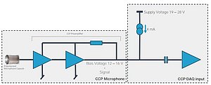
Figure 2. CCP microphone set connection layout including Prepolarized microphone capsule, preamplifier and DAQ input with built in CCP supply.
On the other hand, Traditional preamplifiers must be connected to a power module or an analyzer input which can supply, not only the preamplifier with power, but also +200 V polarization voltage if an externally polarized microphone capsule is used (see Figure 16).
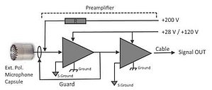
Figure 3. Traditional microphone set connection layout with Externally polarized microphone capsule.
Prepolarized microphones + CCP preamplifier limitations:
As mentioned above, CCP preamplifiers can only be used with Prepolarized microphones.
Dynamic range in CCP preamplifiers is also limited due to its smaller output voltage swing. This is due to the lower driving voltage of a constant-current source which limits the maximum output signal. Effectively, with only an 8-10 Vpeak swing, the upper limit of the amplitude range for the microphone + preamplifier pair is limited by the CCP preamplifier (rather than the microphone itself) by approximately 8-10 dB. Therefore, a ½” microphone with a sensitivity of 50 mV/Pa and an upper dynamic range limit of 146 dB, would now be limited to 138 dB when using a CCP preamplifier.
In comparison, a traditional preamplifier limit is set around 50 Vpeak when using a +/- 60V or +120V supply voltage. This way if we take the same case of the ½” microphone with 50 mV/Pa sensitivity, with a traditional preamplifier it will be possible to reach the upper dynamic range limit of 146 dB (See Figure 17).
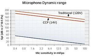
Figure 4. Comparison of upper dynamic range limits of the same microphone using a CCP vs Traditional preamplifier.
Lastly, Prepolarized microphone capsules are slightly more expensive than externally polarized microphones. This is due to the additional manufacturing required to apply the material that contains the electrical charge on the backplate and aging processes needed for adjusting the microphone’s sensitivity. But overall, the cost savings of CCP significantly outweigh this.
The long term and high temperature stability of Prepolarized microphones are typically not as good as for externally polarized microphones. This is because the electrically charged layer of material (on the Prepolarized microphone´s backplate) can lose electrons over time or when exposed to temperatures above its operation range.
What_are_the_benefits_and_limitation_of_using_Prepolarized_microphones_with_CCP.pdf
Are Prepolarized microphones a bad choice for high temperature operation?
Prepolarized microphones have a thin layer of electrically charged material on its backplate. The electrons in this material will provide the polarization voltage needed by the plate capacitor to work.
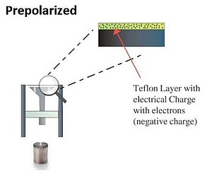
Figure 1. Electrically charged material on the backplate of a Prepolarized microphone capsule.
Depending on the characteristics of the material used, exposure of the capsule to temperatures above 80°C (176°F) for a long period of time, can start degrading the material and allowing electrons to escape the backplate. When this happens, the microphone sensitivity will start falling until the sensitivity is completely lost. The duration of this process will change depending on the microphone, the temperature and the exposure time. Going from hours and up to years. This sensitivity loss is permanent and can’t be recovered without a microphone repair.
If I can’t avoid exposing my prepolarized microphone to high temperatures (that can cause permanent sensitivity loss), but I closelsy monitor the sensitivity change and compensate for it, I can still use that microphone without any issues.
GRAS offers a line of ruggedized microphones that will work with CCP/IEPE/ICP/CCLD supply and can be explosed to temperatures up to 125°C (257°F) WITHOUT permanent sensitivity loss. Check for GRAS 146AE, 147AX and 147EB.
Are_Prepolarized_microphones_a_bad_choice_for_high_temperature_operation.pdf
What is a random incidence corrector?
A random incidence corrector (aka diffuse field corrector) is an accessory that is placed on top of the microphone capsule. This is done in order to change the frequency response of the microphone, that was originally conceived from a specific sound field (i.e. free-field or pressure field), to a diffuse field. Therefore, a microphone with a random incidence corrector will now behave as a random incidence microphone. This is useful when we have, for example, a pressure microphone and we have to perform a measurement in a diffuse field environment (i.e. a reverberant chamber). In this situation, the measurement microphone equipped with a random incidence corrector will give us the possibility of performing the measurement without the need of doing any post-processing for correcting the microphone`s frequency response.
Figure 1. GRAS RA0122 random incidence corrector for ½” free-field microphones.
GRAS offers RA0122 random incidence corrector that can be used with any of our ½” Free-field microphones. We also have RA0357 random incidence corrector, specially designed to be used with our 146AE ½” rugged free-field microphone.
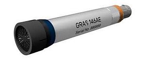
Figure 2. RA357 random incidence corrector placed on GRAS 146AE microphone set.
How is a measurement microphone affecting the sound field?
Any object that is placed in a sound field will cause a disturbance due to its size and shape. A microphone is no different. A standardized IEC-61094-4 WS2P ½” pressure measurement microphone has a diaphragm diameter of 12.6 mm. Let´s imagine a situation where we place the mentioned microphone in a free-field environment (like an anechoic chamber) pointing at 0 degree incidence of an ideal sound source with a flat frequency response (Figure 1).
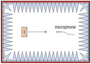
Figure 1. Pressure measurement microphone pointed at 0-degree incidence from a sound source inside an anechoic chamber (Free-field environment).
If we expose this microphone to 100 Hz sine wave coming from the sound source the microphone will be practically “invisible” for this sound wave due to the small size of the microphone (Figure 2) compared to the wavelength of a 100 Hz sine wave (3.4 meters).
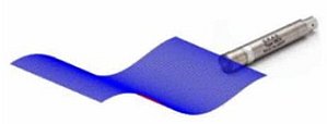
Figure 2. ½” Pressure microphone set exposed to low frequency sound wave with big wavelength.
If we increase the frequency of our reference signal, the wavelength of the signal will start becoming shorter until it starts being comparable with the size of the microphone. For example, a 10000 Hz signal has a wavelength of approx. 34 mm (considering a speed of sound in air of 344 m/s). Under these conditions, we will start noting a diffraction effect happening in front of the microphone diaphragm (Figure 3).
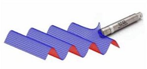
Figure 3. ½” pressure microphone set exposed to high frequency sound wave with short wavelength. Diffraction effect appears.
This diffraction effect will keep increasing with frequency, as the wavelength of the reference signal gets more comparable to the microphone size. The diffraction effect will cause a pressure increase in front of the diaphragm that will be measured by the microphone (Figure 4).

Figure 4. Pressure build-up for a ½” pressure microphone pointing at 0-degree incidence from sound source in a free-field environment.
The higher the frequency, the shorter the wavelength. The shorter the wavelength, the more comparable will be to the size of the microphone and therefore the more diffraction effect. The more diffraction effect, the more pressure build up the microphone will measure. It is important to understand that this measured pressure increase is only a consequence of the microphone being placed in this sound field, and not the frequency response of the loudspeaker (which in this ideal situation has a flat frequency response) or due to reflections (we are supposing a free-field environment, so no reflections are affecting the measurement).
How_is_a_measurement_microphone_affecting_the_sound_field.pdf
Is it possible to measure down to and below the human hearing threshold?
Yes, it is possible if Low-noise microphones are used. Low-noise microphones are measurement microphones with very high sensitivity that are used to measure weak acoustic signals with low sound pressure levels (below 15/20 dB). This means that they can be used to measure and record acoustic signals that can’t be picked up by regular measurement microphones but can be heard by humans. These can be unwanted noises coming from consumer electronic devices like washing

Figure 1. Curves showing the human hearing sensitity. The 20dB line represents the typicall noise floor for a ½” measurement microphone.
machines, laptopts or smart speakers or even in the automotive industry for cabin noise measurements. These signals can be recorded for sound quality evaluation or for signal characterization, in order to improve the device and make it quieter.
The chart below is showing the equal loudness contour curves that describe the sensitivity changes of the typical human hearing system depending on the sound pressure level and frequency. The 20dB line is representing the typical noise floor for a ½” measurement microphone.
Low-noise microphones can typically measure down to 6.5 dBA (GRAS 40HH, 40HL, 40HT and 47HC) which is lower in level than every other standard measurement microphone but above the human hearing threshold. But when we look at frequency bands separately, we can see that it is actually possible to measure below the human hearing threshold of 0dB:

Figure 2. Noise floor for GRAS 40HL low-noise microphone
GRAS also offers the 40HF Low-noise microphone, which is our microphone with the highest sensitivity (1100 mV/Pa). This high sensitivity allows the microphone to be able to measure down to -2 dBA (below the human hearing threshold):

Figure 3. 40HF 1” low-noise microphone noise floor.
Is_it_possible_to_measure_down_to_and_below_the_human_hearing_threshold.pdf
What is special about the rugged NVH microphones?
GRAS 146AE, 147AX and 147EB microphone sets (Figure 43) are the first microphones we released that are specifically designed to overcome some very specific challeges found in Automotive NVH testing. Here there is a list of some of their more impressive charactersitics:
- They are the first water and dust protected measurement microphones in the world (IP67 rated).
- They have an extended temperature performance compared to any other measurement microphone: -40 to 125 ºC (-40 to 257 ºF) without permament sensitivity loss.
- Shock absorbing design: Both the diaphragm and preamplifier’s internal circuitry are protected against the eventual shocks and drops that can happen in rough testing conditions.
- 146AE and 147AX have a power-on indictor for visual confirmation of the microphone status and TEDS chip reading.
- 147EB has three layers of protection to keep the microphone safe while measuring in the toughest conditions, including protection against high particle velocity impacts (like rocks and gravel). It also uses a cable with a rubber sleeve to protect the connector from salty environments and high velocity particle impacts.
- 147AX uses a magnetic mounting system called MagMount™ (Figure 44): The backside of the 147AX microphone housing has a strong built-in magnet which makes it possible to place the microphone on any magnetic surface without compromising the measurements. It is also possible to fix it easily anywhere by using a metal mounting disc allowing for fast, precise and repeatable mounting of the microphone – even in confined spaces.

Figure 1. GRAS Automotive NVH rugged microphones.

Figure 2. GRAS 147AX MagMount™ mounting system
Are there any differences between externally polarized and prepolarized microphones capsules?
A microphone capsule that is classified as a measurement microphone, as defined in IEC 61094 standard family, is of the condenser (also known as capacitor) type.

Figure 1. Condenser/capacitor type measurement microphone diagrams.
In the condenser microphone there are two plates, diaphragm and backplate (See Figure 8), that are separated by an air gap. The backplate is fixed and the diaphragm is the moving part that will move depending on the acoustic pressure in the sound field. When the diaphragm moves up and down it will change the distance (h) between the two plates, changing also the capacitance of the plate capacitor. When this happen the microphone will output a voltage signal variation that will be proportional to the acoustic pressure present in the sound field.
But, just like any other plate capacitor, in order for this to work it is necessary to polarize it. There are two main ways of polarizing a condenser measurement microphone: One is using an external voltage source. The other is adding a layer of pre-polarized electret material on top of the microphone´s backplate that provides polarization voltage without the need of an external voltage source.
Depending on the method used to polarize the microphone capsule, the measurement microphones are divided between these two categories:
- Externally polarized: They require an external source of polarization voltage (usually +200V). These microphone capsules are also called “Traditional” type as they were the first technology of measurement microphone available.
GRAS examples: 40AC, 40AF, 40AG, 40BF, 40BP, 40DP and 40EN.
- Prepolarized: Also known as electret measurement microphones. These types of microphones have a thin layer of electrically charged material on its backplate that will provide the polarization voltage needed for the plate capacitor to work. This means that the microphone capsule itself won’t need any external equipment to provide polarization voltage. As seen in Figure 9, it is possible to differentiate a Prepolarized microphone from an externally polarized thanks to a pair of parallel lines usually present in the Prepolarized capsule.
GRAS examples: 40AE, 40AM, 40AO, 40BD, 40BE and 40DD

Figure 2. Left: ½” externally polarized microphone capsule. Right: ½” Prepolarized microphone capsule

Figure 3. Left: Externally polarized microphone layout with external positive charge polarizing the capsule. Right: Prepolarized microphone with internal negative charge polarizing the capsule.
Figures 10 Left and Right above illustrate basic differences between Externally polarized and Prepolarized microphone capsules.
Are_Prepolarized_microphones_a_bad_choice_for_high_temperature_operation.pdf
What is a microphone set?
Microphone sets are pre-made combinations of microphones capsules with preamplifiers. The measurement microphone sets have been combined so they fulfil our users’ typical measurement needs and applications. Independently of your measurement system and application you should be able to find a set that suits your needs. The microphone sets can be connected directly to all professional measurement systems and, as indicated, they are available for both CCP and Traditional LEMO inputs.
All GRAS measurement microphones sets are composed by two main parts: the microphone capsule and the preamplifier (See Figure 1). The microphone capsule contains the diaphragm, which is designed to move when exposed to a certain range of acoustic pressure variations. On the other hand, the preamplifier is a device designed to transform the high impedance signal coming from the microphone capsule and change it to a low impedance signal that can be fed to a cable. The signal will be then sent to an Analyzer or Data Acquisition System (DAQ). The connector used to get the signal out of the microphone and bring the power to drive the set is usually also in the preamplifier.

Figure 1. GRAS microphone set comprises microphone capsule and preamplifier with connector.
Ordering a microphone set has two main advantages:
- All microphone sets are delivered as a unit and are calibrated accordingly. The sets are delivered with calibration charts including sensitivity values and frequency response curves for the complete set. The sensitivity value can therefore be used directly in your system setup.
- - If your measurement platform supports intelligent transducers according to IEEE 1451.4 (TEDS) you can simply plug in the microphone sets and they will identify themselves with their specific properties, type and calibration data. A feature especially appreciated by multi-channel users. The TEDS chip is stored inside the preamplifier and will be loaded with the sensor data whenever it’s order as a microphone set.
Can dust/dirt affect my measurement microphones?
Dust/dirt can be problematic when in contact with a measurement microphone set. The accumulation of dust in the protection grid can cause its clogging, which will affect the frequency response of the microphone.
Even though a bit of dust on the microphone´s diaphragm won´t affect its performance, the accumulation of it will affect the microphohone`s sensitivity due to the added mass.
Dust/dirt can affect the contacts between microphone and preamp and the preamplifier cable connector pins. Therefore it is advised not to expose these parts in dusty environments. Dirty contactc can higher the noise floor of the microphone or completely block the signal.
Venting holes in preamp and/or microphone capsule can be clogged by dust or dirt. When this happens the microphone can´t equalize its internal pressure with the outside pressure and measured data won´t be reliable.
Both microphones (including its diaphragm) and preamps are cleaned by our experts when sent for calibration or repair to GRAS calibration laboratories.
GRAS offers a line of ruggedized microphones that are ready to work in demanding environments with dust/dirt. Check for GRAS 146AE, 147AX and 147EB.
What is the maximum level I can measure with a typical ½” free-field microphone?
The maximum level a microphone can handle is usually specified as the “dynamic range upper limit”. If we look at ½” measurement microphones, we can see that this limit can be different between microphones that look exactly the same. That is because this parameter will be affected by the sensitivity of the microphone (usually specified in mV/Pa or dB). It is also possible to find ½” microphones with very different sensitivities. Therefore, a ½” measurement microphone of 50 mV/Pa sensitivity can have an upper dynamic range limit of 149 dB, while another ½” microphone of 12.5 mV/Pa sensitivity will have a limit of 164 dB. The lower the sensitivity, the higher the upper dynamic range limit.
The upper dynamic range limit will be also detertmined by the type of preamplifier used and its power supply. GRAS offers both Traditional and CCP (also known as IEPE/ICP/CCLD) preamplifiers.
Dynamic range in CCP preamplifiers is limited due to its smaller output voltage swing. This is due to the lower driving voltage of a constant-current source which limits the maximum output signal. Effectively, with only an 8-10 Vpeak swing, the upper limit of the amplitude range for the microphone + preamplifier pair is limited by the CCP preamplifier (rather than the microphone itself) by approximately 8-10 dB. Therefore, a ½” microphone with a sensitivity of 50 mV/Pa and an upper dynamic range limit of 146 dB, would now be limited to 138 dB when using a CCP preamplifier.
Finally, very long cables can also limit the dynamic range upper limit of a microphone set, but that is another topic.
What_is_the_maximum_level_I_can_measure_with_a_typical_1-2_free-field_microphone.pdf


